iAS : Industrial Automation Suite
"iAS" (Industrial Automation Suite) คือ ชุดเครื่องมือสำหรับการควบคุมและการจัดการระบบอัตโนมัติในอุตสาหกรรม ซึ่งครอบคลุมการรวมระบบต่างๆ ในโรงงานหรือการผลิต เพื่อเพิ่มประสิทธิภาพ ลดความผิดพลาด และเพิ่มความคล่องตัวในการทำงาน โดย IAS ได้รวบรวมทั้ง ซอฟต์แวร์ และฮาร์ดแวร์ต่างๆ ที่ใช้ในการวางแผน ตรวจสอบ และควบคุมกระบวนการอัตโนมัติในอุตสาหกรรม ซึ่งอาจรวมถึงการควบคุมเครื่องจักร, การตรวจสอบข้อมูลการผลิต, การจัดการพลังงาน, และการบำรุงรักษา เป็นต้น
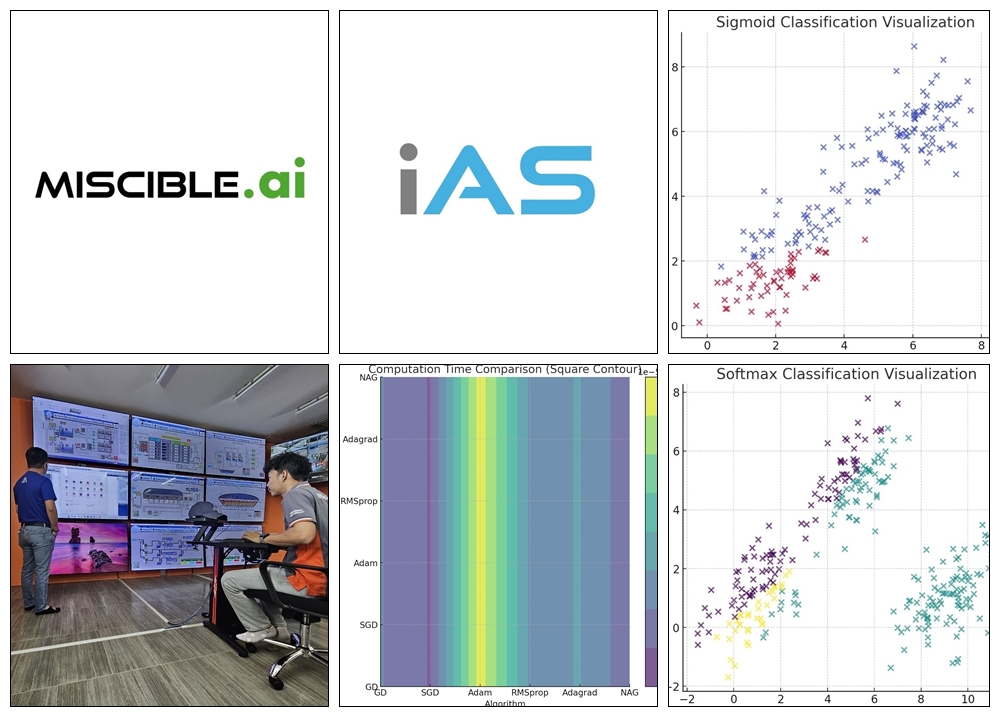
บริษัทฯ ของเราเชี่ยวชาญในการออกแบบและติดตั้งระบบ Factory Automation ด้วย SCADA-PLC พร้อมต่อยอดนำ Big Data ที่ได้มาพัฒนาโมเดล AI เพื่อเพิ่มประสิทธิภาพและความแม่นยำในการดำเนินงาน ไม่ว่าคุณจะต้องการควบคุมการผลิตอัตโนมัติหรือใช้ AI ในการวิเคราะห์ข้อมูล เรามีความพร้อมในการให้บริการแบบครบวงจรเพื่อพัฒนาธุรกิจของคุณสู่ความสำเร็จในยุคดิจิทัล