In-Tank Shaft Configuration
In-Tank Shaft Configuration
The shaft configuration selected for a specific mixer application depend on the process requirements such as 'the tank geometry', 'the drive unit', and 'economics'. The selection usually requires analyzing more than one design. However, the final selection must also meet the drive limitations.
The way of the shaft is supported and coupled to the drive is an important consideration. There support and coupling determine the force and moment transfer between the drive and the in-tank shaft. These force and moment affect the bearing service life. the drive gear bearing, and housing deflections. Most manufacturers publish overhung load limitation for the output shaft of their drive.
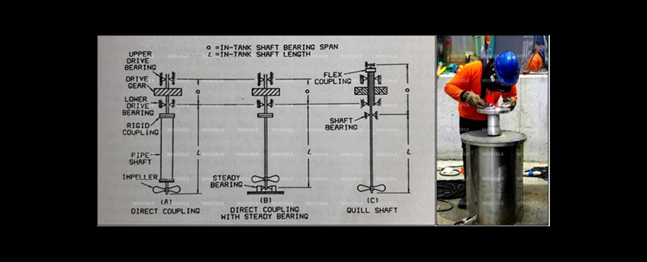
The illustrates different shaft supporting and coupling methods for three in-tank shaft configurations for top entry agitators, The direct coupled shaft (Fig-A) is supported by drive bearing and is drive by the the drive output gear. In this arrangement, the lower shaft is designed to carry only the impeller loads, and the upper portion is designed to carry both the impeller loads and the gearing reactions. Consequently, the load-carry capacity of the lower shaft is limited by the capacity of the upper drive shaft.
The direct-coupled shaft with steady bearing (Fig-B) used for very long shafts which exceed either the shaft limitations of the drive or the critical speed limitations. The steady bearing reduces the drive reaction and gearing deflections. This reduction generally places the bending moment created by the impeller within the shaft limitations of the drive.
In Fig-C, the quill shaft configuration has two shafts connected by a flexible coupling which primarily transmit torque. This arrangement isolates the drive shaft from the bending moments and thrust of the agitator shaft. The agitator shaft has two independent bearings which are usually mounted on the top and bottom of the drive housing. This top and bottom arrangement has a larger bearing span than that of the direct-coupled shaft. Larger bearing span give smaller bearing reactions for the same overhung loads.
ในส่วนของมาตรฐานการออกแบบของบริษัทฯ
1. เลือกใช้ Solid Shaft เป็นอันดับแรกหากไม่ถูกจำกัดโดยงบประมาณของลูกค้า
2. หากใช้ Hollow Shaft ต้องใช้ Steady Bearing เท่านั้น
3. เพลายาวไม่เกิน 2.5 เมตร อาจจะ ไม่ต้องใช้ Steady Bearing
4. เพลายาวเกิน 3.0 เมตร ต้องใช้ Steady Bearing
5. เพลายาวเกิน 9.0 เมตร ต้องใช้ Steady Bearing 2 Stages
ขอบคุณครับ
สถาพร เลี้ยงศิริกูล (Agitator Designer)
MISCIBLE TECHNOLOGY CO., LTD
Tel: 02.548.0414-5 / 091.7400.555
Line : @agitator
www.miscible.co.th